This note explains the relationship between the noise floor of the spectrum analyzer and the internal attenuator (ATT).
Application
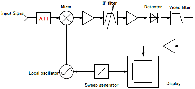
The figure below shows a simplified block diagram of the spectrum analyzer. If a signal exceeding the appropriate level is applied to the mixer input, harmonic distortion and spurious will occur due to saturation, and correct measurement will not be possible.
To prevent this, an internal ATT is inserted before the mixer.
Simplified block diagram
The following shows the result of measuring the noise floor with no RF signal input and changing the internal ATT of the spectrum analyzer.
(In the MSA series, the internal ATT value is automatically set according to the reference level setting value.
Refer to “Relation between reference level and ATT / AMP” in the instruction manual.)
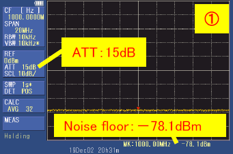
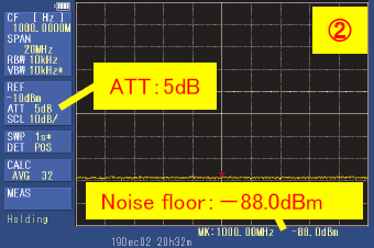
When the internal ATT is lowered by 10 dB as shown in ① → ②, the noise floor is also reduced by 10 dB.
Since the noise floor is determined by the circuit after the internal ATT, the fluctuation amount of the internal ATT directly corresponds to the noise floor.
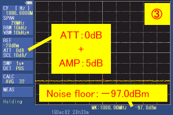
In case of ② → ③, internal ATT is lowered by 5dB, and internal amplifier (AMP) 5dB is added.
Simply think, the noise floor is reduced by 10 dB, but because of the internal AMP noise, it is reduced by 9 dB.
Even when ATT or AMP is connected to the outside of the spectrum analyzer, the noise floor will also fluctuate.
System configuration
| Handheld signal analyzer MSA500 series |
| Handheld spectrum analyzer MSA400 series |
Products introduction
Handheld signal analyzer MSA500 series
With Fast Fourier Transform (FFT) and conventional sweep systems, each strong point of both systems is usable.
[product_category category="shop-category-msa500" orderby="date" order="asc" columns="3"]Handheld Spectrum Analyzer MSA400 Series
MSA300 series was extremely upgraded to MSA400 series.This product has large color display.
[product_category category="shop-category-msa400" orderby="date" order="asc" columns="3"]
Please feel free to contact us.
If you want to verify 5G, customize a radio wave shield box, or need product repair, please do not hesitate to contact us about any small matter.