Optium tool for analysis of high-frequency circuit design (High-frequency passive probe MP300)
Application
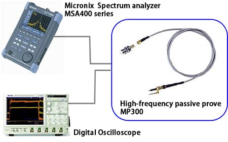
MP300 is a passive probe that has a wide frequency range and low input capacitance. It is used in connected with measurment equipment (Spectrum analyzer or Oscilloscope). Danping ratio is 10:1 for that MP300's input resistance is 500Ω. Its ratio is quite lower than popular passive probe and FET probe.
Operator is demanded a little attention when measure the circuit in low frequency range (DC-XXKHz) However,since this probe is low input capacitance and low impedance, it has favourable frequency response in high frequency range. It is useful for analysis and diagnostics on high-frequency circuit design.
Solution
Configuration
Performance table
| Item | Specification |
|---|---|
| frequency bandwidth(-3dB) | 6GHz |
| attenaution ratio | 10:1±2% (50Ω±1% connected load) |
| input resistance | 500Ω±2% (50Ω±1% connected load) |
| input capability | 0.25pF(typ) |
| cable length | 1m |
| connector shape | SMA |
| input voltage endurance | 10Vrms, 20Vpeak(PW<1ms) |
| operating temperature range | 5 to 35°C |
| operating humidity range | Less than 85%RH (non condensing) |
| storage temerature range | -20 to 70°C |
Probe comparison table
| Probe | input impedance | output impedance | measurement Frequency range (roughly) |
Recital | |
|---|---|---|---|---|---|
| R | C | ||||
| Oscillo
probe (10:1) |
10MΩ | 10pF | 9MΩ | DC to 200MHz | Adjusting phase of the probe is required |
| FET Probe | 100KΩ | 1 to 4pF | 50Ω | DC to 1000MHz | DC power supply is required |
| MP300 | 500Ω | 0.25pF | 50Ω | DC to 6GHz | input impedance is a little lower |
Fig of simple circuit component
Suit for comparison of simulation results and failure analysis on design of high-frequency.
*Indicate is 20dB lower than a given level by using 50Ω line measuring equipment for that probe input impedance is 500Ω.
*20 log 50 / 500
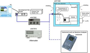
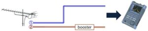
If this circuit is inputted 0dBm.Since there are three 10dBm amplifers on it, Implicit output level is +30dBm. When 50 Ω lines Measuring equipment doesn't indicate +10 dBm on output point. ,there is a defect on this cirucuit. Measuring each point (P1,P2,P3,P4,) by using this probe that can caluculate where circuit defect arise.
Products introduction
[product sku="mp300"]
Please feel free to contact us.
If you want to verify 5G, customize a radio wave shield box, or need product repair, please do not hesitate to contact us about any small matter.