MSA500 series Signal Analyzer offers strong trigger functions on real-time mode.
On this document, the way to operate and some examp les are introduced.
Trigger Source Selection
At first the trigger source described below should be selected when the trigger function is used.
| Free Run: | The waveform is updated without any condition. |
|---|---|
| IF Level | Trigger condition is defined as the ratio between the instantaneous signal level and the full scale of IF signal path. If the signal level exceeds the trigger level, the waveform is updated. |
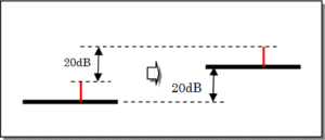
| Power | Trigger condition is defined as t he total power within the span. Trigger level is described as the relative value ag ainst the reference level. When the trigger slope is set to "RISE", if the sig nal power exceeds the trigger level, the waveform is updated. When the trigger slope is set to "FALL", if the sign al power is lower than the trigger level, the waveform is updated. |
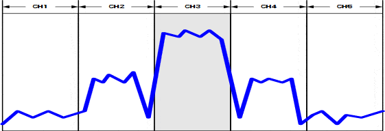
| Channel Power | Trigger condition is defined as the total power within the channel. The span is divided into 5 then each piece is defined as the channel. Trigger level is described as the relative value against the reference level. The trigger slope setting works as same as Power trigger. |
| External | Trigger condition is defined as the external trigger input voltage. When the trigger slope is set to "RISE", if the inp ut level exceeds the fixed threshold (0.56V), the waveform is updated. When the trigger slope is set to "FALL", if the input level is lower than the fixed threshold(0.56V), the waveform is updated. |
The comparison table is shown in below. Please refer to the table at section 7 for the sample time.
| Trigger Source | Time Resolution | Slope | Level Range |
|---|---|---|---|
| IF Lever | 14.7ns | RISE only | 1 to 100 %(1% Step) |
| Power | 1sample | RISE/FALL | -40 to 0 dB(1dBStep) |
| Channel Power | 5sample | RISE/FALL | -40 to 0 dB(1dBStep) |
| External | 14.7ns | RISE/FALL | 0.56V Fixed |
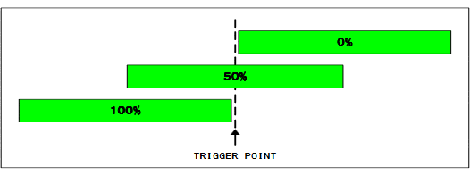
Pre-Trigger Setting
Pre-Trigger defines how many data is captured before the trigger event.
It is available to choose 0/25/50/75/100%.
Trigger Slope Setting
This is the choice of the trigger slope "RISE" or " FALL". Please refer to "1" for the operation.
Scan Setting
This is the choice of the waveform update is one ti me (Single) or repeatable (Continuous).
Trigger Level Setting
| IF Level | Set as the ratio against the ful l-scale. 1 to 100% at 1% step. |
|---|---|
| Power | Set as the relative value against the ref erence level. 0 to –40dB at 1dB step. |
| Channel Power | Set as the relative value against the reference level. 0 to –40 dB at 1 dB step. |
Trigger Channel Setting
| Channnel Power | Choice of the one of 5 channels to be used as the trigger source. 1 is the lowest frequency, 3 is the center and 5 is the highest frequency. |
|---|
Acquisition Frame Setting
It sets the acquisition length as the frame count.
The setting menu is available with pressing "OPERATION MODE" button.
Press "ACQ FRAME" (F3) then set the frame count by the encoder.
"ENC STEP"(F6) offers the step size setting of the encoder.
1frame consists of 1024 sample on time domain.
Sample/Frame time and maximum acquisition time depe nds on the span setting as follows.
| Span | Sample Time | Frame Time | Maximum Acquisition Time |
|---|---|---|---|
| 20MHz | 29.4ns | 30.1us | 0.4935s |
| 10MHz | 58.8ns | 60.2us | 0.9869s |
| 5MHz | 118ns | 121us | 1.973s |
| 2MHz | 294ns | 301us | 4.935s |
| 1MHz | 588ns | 602us | 9.869s |
| 500kHz | 1.18us | 1.21ms | 19.73s |
| 200kHz | 2.94us | 3.01ms | 49.35s |
| 100kHz | 5.88us | 6.02ms | 98.69s |
| 50kHz | 11.8us | 12.1ms | 197.3s |
| 20kHz | 29.4us | 30.1ms | 493.5s |
Main Analysis Setting
Main Analysis can be set on the menu of "ANALYSIS M AIN"(F1) under "OPERATION MODE" key.
| Spectrum | Spectrum Analysis is set. Analysis frame count is fixed to 1. |
|---|---|
| Spectrogram | Spectrogram Analysis is set. |
| Overwrite | Overwrite Analysis is set. Trigger source is fi xed to Free Run. |
| Time Domain | Time Domain Analysis is set. Further selection is sh own in below.
|
Sub Analysis Setting
Sub Analysis can be set on the menu of "ANALYSIS SUB" (F2) under "OPERATION MODE" key.
- Power vs. Time: Y axis is set to Power [dBm]
- Spectrogram: Spectrogram Analysis is set.
- Off:Sub Analysis is disabled.
Start of Acquisition
Press "HOLD/RUN" to start. Press "HOLD/RUN" again to stop.
Example
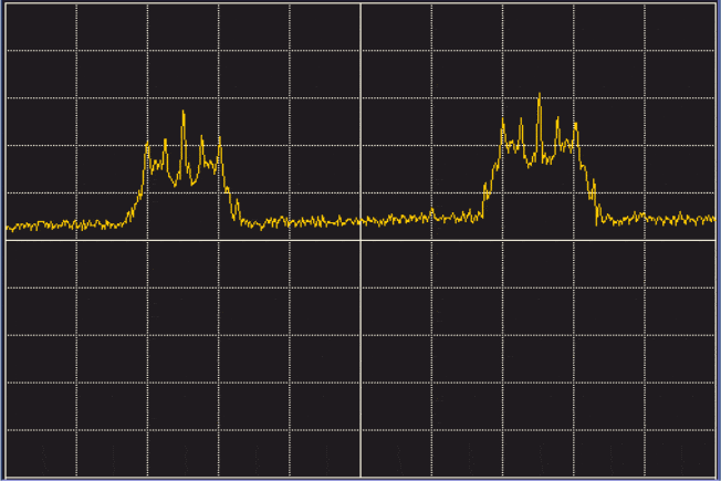
- Intermittent Spectrum Capturing
At this example, MSA500 captures the intermittent signal generated by the transmitter
[Setting Procedure]
- On Real-time mode, Center Frequency, Span and Reference Level is set as desired.
- Press "TRIG" - "TRIG SRC SELECT" [F1] - "IF LEVEL" [F4] then set IF LEVEL to 5%
- Press "RETURN"[F6] – "SCAN"[F4] then set to "CONTINUE "
- Press "OPERATION MODE" – "ANALYSIS MAIN"[F1] then select "SPECTRUM
- Press "RETURN"[F6] – "ANALYSIS SUB"[F2] then select "OFF"[F3]
- Press "CALC" – "MAX HOLD"[F2] the set hold count to " **"
- Press "HOLD/RUN" to start acquisition
- When the signal is captured, Press "HOLD/RUN" to stop the acquisition
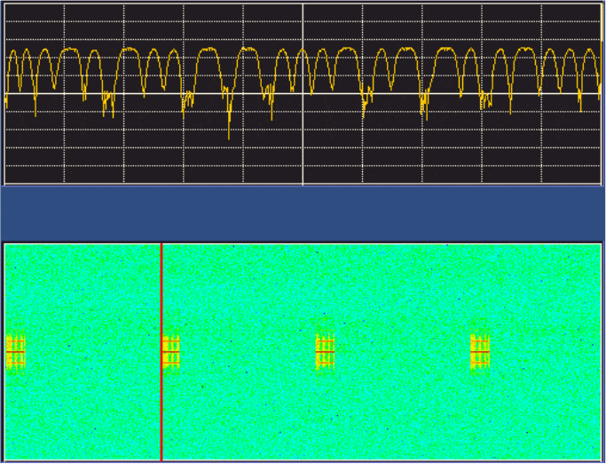
- ASK signal analysis generated by ETC road side unit
We analyze ASK signal with split phase coding on this example.
[Setting Procedure]
- On Real-time mode, Center Frequency, Span and Refere nce Level is set as desired.
- Press "TRIG" - "TRIG SRC SELECT"[F1] - "POWER"[F2] then set POWER to -35dB
- Press "RETURN"[F6] – "SLOPE"[F3] RISE, "SCAN"[F4] then set to "SINGLE"
- Press "OPERATION MODE" – "ANALYSIS MAIN"[F1] - "T DOM AIN"[F4] – "POWER-T"[F1]
- Press "RETURN"[F6] – "ANALYSIS SUB"[F2] - "SPECTROGM" [F2]
- Press "RETURN"[F6] – "ACQ FRAME"[F3] then set to 500
- Press "HOLD/RUN" to start acquisition
- When acquisition is completed, adjust "STT FRAME"[F4], and "ANL FRAME"[F5] to set the analysis window for Main analysis.
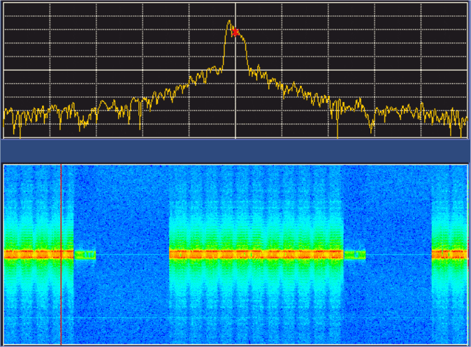
- Transmit time measurement of Smartmeter signal
We measure the transmit time of the GFSK signal generated by Smartmeter.
By the measurement below,- Frame time:301[us] @2M span
- Transmit Frame count:754
- Transmit Time:0.301 x 754 = 226.9 [ms]
- On Real-time mode, Center Frequency, Span and Refere nce Level is set as desired.
- Press "TRIG" - "TRIG SRC SELECT"[F1] - "POWER"[F2] then set POWER to -35dB
- Press "RETURN"[F6] – "PRE TRIG"[F2] 0% , "SLOPE"[F3] "RIS E", "SCAN"[F4] to "SINGLE"
- Press "OPERATION MODE" – "ANALYSIS MAIN"[F1] - "T DOM AIN"[F4] – "POWER-T"[F1]
- Press "RETURN"[F6] – "ANALYSIS SUB"[F2] - "SPECTROGM" [F2]
- Press "RETURN"[F6] – "ACQ FRAME"[F3] then set to 2000
- Press "HOLD/RUN" to start acquisition
- When acquisition is completed, adjust "STT FRAME"[F4], and "ANL FRAME"[F5] to set the analysis window for Main analysis.
Products introduction
Handheld signal analyzer MSA500 series
With Fast Fourier Transform (FFT) and conventional sweep systems, each strong point of both systems is usable.
[product_category category="shop-category-msa500" orderby="date" order="asc" columns="3"]
Please feel free to contact us.
If you want to verify 5G, customize a radio wave shield box, or need product repair, please do not hesitate to contact us about any small matter.