Floor arrangement
The measurement example using MSA338 is explained by “Floor arrangement” of the figure below. The electric field strength is measured in th e parts enclosed with circle from 1 to 2. And it is assumed that two access points are installed on the locker and are set to the different channels.
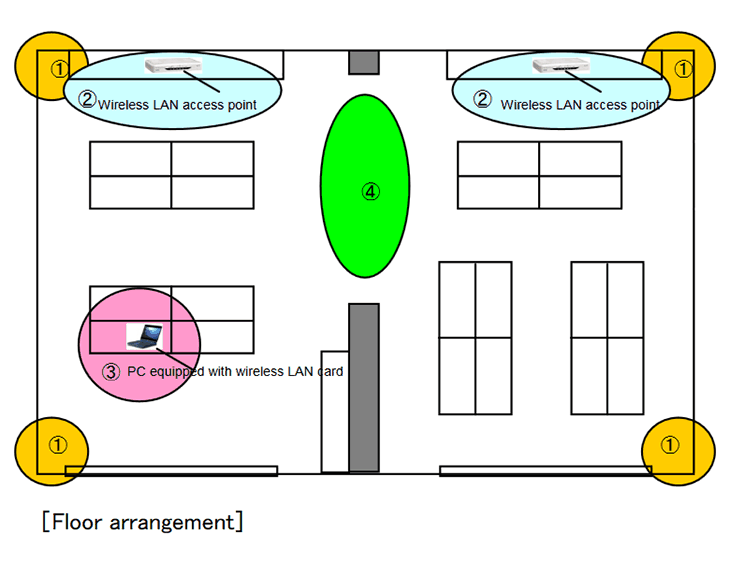
- The radio wave state in the floor is measured at the four corners before the access point is installed.
- The access points are temporarily installed at the positions shown in the above figure and are set to the different channel number, and then the electric field strength is measured.
- The access points are fixed, and then the electric field strength is measured moving a notebook PC with a wireless LAN card.
- The waveform’s examples in which the radio wave interferes with other one and doesn’t at the access points shown in the above figure.
The setting of MSA338 is as follows when not specified especially.
- Center frequency[FREQ]:2.44GHz
- Frequency span[SPAN]:100MHz
- Resolution bandwidth[RBW]:1MHz
- Video bandwidth[VBW]:OFF
- Reference level[REFER]:-30dBm
- Sweep time[SWEEP]:0.1s
- Calculation[CALC]:MAX
However, the channel number14 of the wireless LAN goes outside right of the screen if the center frequency is not changed to 2.45GHz, because the number of channels is assumed thirteen at the above setting. Moreover, it is necessary to increase or decrease the reference level by about 10dBm depending on the environment. The electric field strength measurement can be done by pushing [MEAS] key and by selecting the electric field strength measurement mode by [F4] key, and then by selecting [M304] as an antenna by [F1] key. However, it is not necessary to use the electric field strength measurement mode if the unit of standard is dBm or W. It is better that the receiving power is measured in the cha nnel power measurement mode because the antenna gain changes little at the span 100MHz.
The channel power measurement can be done by pushing [MEAS] key and by selecting the channel power measurement mode by [F1] key, and then by selecting BAND by [F1] key. Secondly, the center (CNTR) and width (BAND) of the measured channel are set. The width, usually, is fixed to 20MHz. With the setting mentioned above , the receiving power of the sp ecified channel is displayed on the screen. However, if the channel power measurement mode is not turned of f while measuring, the measurement time becomes long.
Moreover, it is necessary to wait for considerable long time in the state of measurement in order to obtain a clear waveform, because the radio wave is periodically radiated only for a short time when the communication is not performed. A clear waveform can be obtained in a short time if a large amount of data can be compulsorily output.
he measurement example of the radio wave state which was measured at the four corners of the floor before installation of the access point
It is confirmed whether the disturbance noise and other access points exist by observing the radio wave in the range from 2400 to 2483.5MHz.
Photo1
[Conclusion]
Any radio wave was not observed except at the setting frequency range (2.427 to 2.447GHz) of the access point.
The measurement examples of the electric field strength in the state that the access p oints are temporarily installed and are fixed to the different channel number
Photo2:One access point (channel1)
[Conclusion]
The bandwidth of the channel1 is about 20MHz and any other unnecessary spectrum is low level. Therefore, no problem.
Photo3:Two access points (channel1 and channel5)
[Conclusion]
Channel 1 and channel 5 can communicate without interference because two channels are 20MHz away.
③ The access points are fixed, and then the electric field strength is measured moving a notebook PC with a wireless LAN card.
Photo4:Wireless LAN card (No disturbance)
[Conclusion]
When a wireless LAN card exists near, there is a possibility that other radio waves ca nnot be measured because the output power of the card is too large.
In Photo4, the signals of the access point of channel1 and the wireless LAN card of channel5 are observed.
④ The waveform’s examples in which the radio wave of the access points interferes and doesn’t at the middle point of two access points.
Photo5:Interference(channel1 and channel3)
[Conclusion]
The waveforms of channel1 and channel3 overlap partially because two signals are only 10MHz away.
Photo6:No interference (channel1 and channel5)
[Conclusion]
The waveforms of channel1 and channel5 don’t overlap because two signals are 20MHz away.
Photo7:No interference (channel1 and channel13)
[Conclusion]
The waveforms of channel1 and channel13 are completely separated because two signals are 60MHz away.
Products introduction
[product sku="msa338"]
Please feel free to contact us.
If you want to verify 5G, customize a radio wave shield box, or need product repair, please do not hesitate to contact us about any small matter.