The method of measuring the output of BS/CS converter using handheld real time signal analyzer will be introduced.
Application
Connection block diagram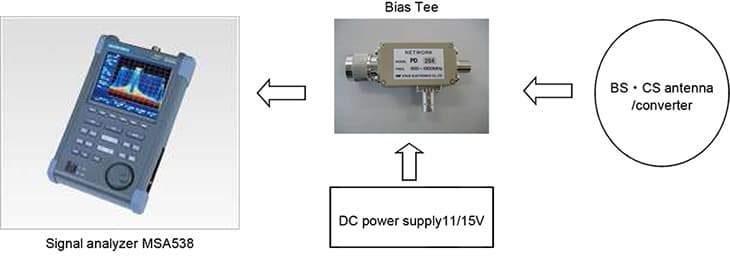
Solution
- The satellite signal of 12GHz band is converted to IF frequency from 1.5 to 2GHz by BS · CS antenna / converter.
- Bias Tee will convert the impedance from 50Ω at spectrum analyzer side to 75Ω at antenna side, and also supply the power to BS/CS converter.
- Bias Tee is supply the power from the external. The polarization plane of the antenna can be changed by switching the voltage of 11/15V.
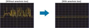
- The time response of frequency and power can be observed using the spectrogram function of signal analyzer.
- Similarly, the temporal variation of power and phase will be observed using the time domain function. The figure below shows the time response of power.
System configuration
| Spectrum Analyzer[MSA538] | x 1 |
| Bias Tee [PD264] | x 1 |
| DC power supply 11/15V | x 1 |
| Cables | x 1 |
Products introduction
[product sku="msa538"]
Please feel free to contact us.
If you want to verify 5G, customize a radio wave shield box, or need product repair, please do not hesitate to contact us about any small matter.