Power Line Noise Monitoring Equipment
Power Line Noise Monitoring Equipment
- 1. Power Line Noise Monitoring Equipment
- 2. Main equipment configuration and flow to measurement
- 2.1. 1. Handheld Spectrum Analyzers and Signal Analyzers, Magnetic Field Probes
- 2.2. 2. PC for measurement, logging software
- 2.3. 3. Setup
- 2.4. 4. Measurement
- 2.5. 5. Playback
- 3. When considering introduction
- 4. Library
- 4.1. Products Catalog
Power Line Noise Monitoring Equipment
Most of the power outlets in a normal tenant building or factory do not have a stand-alone electrical system, and many unspecified load facilities are connected between the distribution board and each facility. When using electronic equipment/facility electricity, noise generated from the secondary side may follow the relevant path and affect other electrical equipment and home appliances. If the power supply line is aging and bare, depending on the state of deterioration, it may become an antenna, amplifying unwanted noise components, or drawing in disturbing noise from the connector contact area, which can cause unexpected problems. In addition, the frequency of troubles due to radio interference may change due to fluctuations in the amount of noise when there are many so-called load devices, such as a large number of people.
When trying to monitor these state changes, it is essential to visualize the noise components that occur unexpectedly. By making it easier to grasp changes in conditions, such as the frequency of regular occurrences or the environment of the secondary power line at the location of the failure, it is possible to find more directions for countermeasures against recurrence and improvements in facility layout.
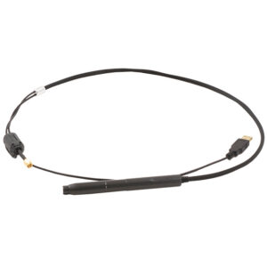
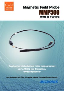
There have been many noise monitoring systems for these power supply lines in the past, and they are used in a variety of fields. Our handheld spectrum analyzers are also widely used for both conducted and radiated noise suppression. One of the main features of monitoring equipment using spectrum analyzers is the advantage of enabling frequency monitoring over a wide bandwidth. In addition to capturing instantaneous noise, it is also capable of recording the state of the frequency components at the time of noise generation. By combining these characteristics with logging software using a PC, we have accumulated a track record mainly in the field of air measurement, such as unmanned measurement of illegal noise source monitoring and continuous monitoring of satellite wave reception. By setting up the magnetic field probe MMP500 here, it has become possible to support constant monitoring of power line noise in a simpler form. This is a form in which the characteristics of the probe, which can be measured electrically non-contactly, are incorporated into conventional noise monitoring equipment. In addition, MMP500 can be used not only with our spectrum analyzer but also with a spectrum analyzer made by another company that you already have.
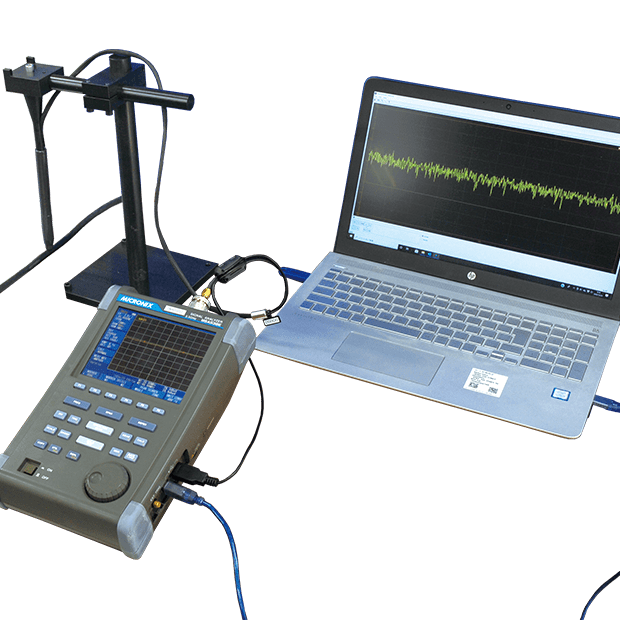
Main equipment configuration and flow to measurement
This system mainly consists of a handheld spectrum analyzer/signal analyzer, a magnetic field probe, a PC for measurement, and logging software.
The flow from the configuration of the system equipment to the actual measurement is as follows.
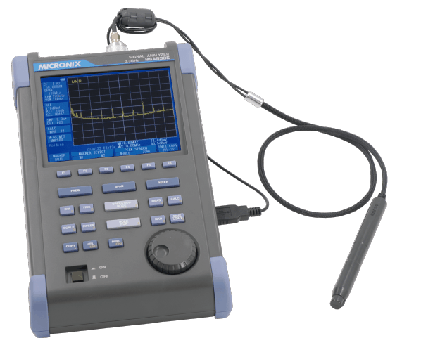
1. Handheld Spectrum Analyzers and Signal Analyzers, Magnetic Field Probes
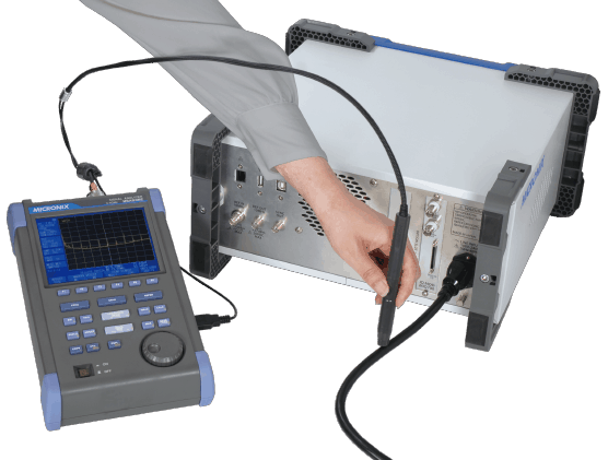
Connect the analyzer to the magnetic field probe.
Please refer to the following video for the connection procedure between the two units. (The setting procedure differs from the video content.)
The calibration coefficients for the magnetic field probe are included in the shipment. Corrections are required when combining with a spacer made by another manufacturer.
2. PC for measurement, logging software
Prepare a suitable PC for measurement in consideration of the installation location. Install the logging software on the PC.
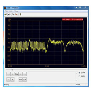
Logging Software MAS410/510
Software that displays spectral waveforms on a PC screen.
- Category
- Spectrum Analyzer and Spectrum Analyzer Option
3. Setup
After completing the settings of 1 and 2, then actually start the logging software, check the waveform, and prepare for measurement. The measurement is performed in the recording mode of the software. At this time, please note that it is necessary to insert the dedicated dongle key into the PC.
If the target frequency range has been determined beforehand, specify the appropriate frequency range in the logging software, and then set the necessary parameters. The recording time depends on the remaining HDD capacity of the measurement PC. Prepare an appropriate HDD capacity after considering the measurement interval and threshold setting.
We recommend that you start with a test measurement with a short time setting (optional), and after confirming the operation, shift to the main measurement.
The magnetic field probe must be fixed. As shown in the following video, align the arrow of the magnetic field probe with the target power supply line and fix it (the direction of ± does not matter).
After fixing the magnetic field probe, actually perform a test measurement from the recording mode screen of the logging software. If there seems to be no problem, start this measurement.
4. Measurement
Logging software (after setting each parameter) → After specifying the data storage location, select the recording mode screen. → Press the [REC] button to start measurement.
5. Playback
Logging software→ After reading the saved data, select the playback mode screen → Use the [Track Bar] and [Control Button] to start playback.
When considering introduction
The power line noise monitoring equipment system supports customization of the measurement environment in a wide range of forms.
If you want to check the measurement image, please contact our sales staff.
Library
Products Catalog


Please feel free to contact us.
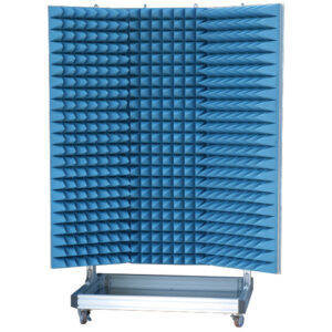
If you want to verify 5G, customize a radio wave shield box, or need product repair, please do not hesitate to contact us about any small matter.